
A gas carrier (or gas tanker) is a ship designed to transport LPG, LNG or liquefied chemical gases in bulk.
Gas Tanker Basics – Definitions
The International Maritime Organization (IMO), for the purposes of its Gas Carrier Codes, has adopted the following definition for the liquefied gases carried by sea:
1. Gas
Liquids with a vapour pressure exceeding 2.8 bar absolute at a temperature of 37.8°C
2. Boiling Point
The temperature at which the vapour pressure of a liquid is equal to the pressure on its surface (the boiling point varies with pressure)
3. Cargo Area
That part of the ship which contains the cargo containment system, cargo pumps and compressor rooms, and includes the deck area above the cargo containment system. Where fitted, cofferdams, ballast tanks and void spaces at the after the end of the aftermost hold space or the forward end of the forwardmost hold space are excluded from the cargo area.
4. Cargo Containment Systems
The arrangement for containment of cargo including, where fitted, primary and secondary barriers, associated insulations, interbarrier spaces and the structure required for the support of these elements.
5. Gas-Dangerous Space or Zone
A space or zone within a ship’s cargo area which is designated as likely to contain flammable vapour and which is not equipped with approved arrangements to ensure that its atmosphere is maintained in a safe condition at all times.
6. Gas-Safe Space
A space on a ship not designated as a gas-dangerous space.
7. Hold Space
The space enclosed by the ship’s structure in which a cargo containment system is situated.
8. Interbarrier Space
The space between a primary and a secondary barrier of a cargo containment system, whether or not completely or partially occupied by insulation or other material.
9. MARVS
This is the abbreviation for the Maximum Allowable Relief Valve Setting on a ship’s cargo tank — as stated on the ship’s Certificate of Fitness.
10. Primary Barrier
This is the inner surface designed to contain the cargo when the cargo containment system includes a secondary barrier.
11. Secondary Barrier
The liquid-resisting outer element of a cargo containment system designed to provide temporary containment of a leakage of liquid cargo through the primary barrier and to prevent the lowering of the temperature of the ship’s structure to an unsafe level
12 Tank dome
It is not permitted for a cargo pump room to be placed below the upper deck, nor may cargo pipelines are run beneath deck level; therefore, deep well or submersible pumps must be used for cargo discharge. Pipelines to cargo tanks must be taken through a cargo tank dome which penetrates the deck.
Different Types of Gas Tanker Ships
Gas carriers can be grouped into five different categories according to the cargo carried and the carriage condition. These are as follows:
- Fully pressurised ships
- Semi-pressurised ships
- Ethylene ships
- Fully refrigerated LPG ships
- LNG ships
The first three ship types listed are most suitable for the shipment of smaller-size cargoes of LPG and chemical gases. This is normally accomplished on short-sea and regional routes. Fully refrigerated ships are used extensively for the carriage of large size cargoes of LPG and ammonia on the deep sea routes.
1. Fully pressurised ships
- Fully pressurised ships are the simplest of all gas carriers. They carry their cargoes at ambient temperature.
- They are fitted with Type ‘C’ tanks (pressure vessels) fabricated in carbon steel having a typical design pressure of about 18 barg. Ships with higher design pressures are in service and a few ships can accept cargoes at pressures of up to 20 barg.
- No thermal insulation or reliquefaction plant is necessary for these ships and cargo can be discharged using either pumps or compressors.
- Because of their design pressure, the cargo tanks are extremely heavy. As a result, fully pressurised ships tend to be small having cargo capacities of about 4,000 to 6,000 m3, and are primarily used to carry LPG and ammonia.
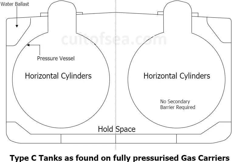
- Ballast is carried in double bottoms and in top wing tanks. Because these ships are fitted with Type ‘C’ containment systems, no secondary barrier is required and the hold space may be ventilated with air.
Advantages of fully pressurized tankers:
i) They are built with ordinary grades of steel as the cargo is carried at ambient temperature and no insulation is required
ii) no reliquefaction plant is required
iii) operations are simpler
Disadvantages
i) Due to their shape, the use of underdeck space cannot be optimised
ii) high design pressure requires considerable tank wall thickness, with consequent increase in displacement weight and cost
2. Semi-pressurised ships
- Semi-pressurised ships are similar to fully pressurised ships in a context that they have Type ‘C’ tanks — in this case, pressure vessels designed typically for a maximum working pressure of from 5 to 7 barg. Compared to fully pressurised ships, a reduction in tank thickness is possible due to the reduced pressure but this is at the cost of refrigeration plant and tank insulation.
- This type of gas carrier has evolved as the optimum means of transporting a wide variety of gases such as LPG, vinyl chloride, propylene, and butadiene. They are most frequently found in the busy coastal trades around the Mediterranean and Northern Europe. Today, this type of ship is the most popular amongst operators of smaller-size gas carriers due to its cargo handling flexibility.
- Semi-pressurised ships use Type ‘C’ tanks and, therefore, do not require a secondary barrier (cargo capacities can vary from 3,000 to 20,000 m3). The tanks are usually made from low-temperature steels to provide for carriage temperatures of -48°C which temperature is suitable for most LPG and chemical gas cargoes.
- Alternatively, they can be made from special alloyed steels or aluminium to allow for the carriage of ethylene at -104°C (see also ethylene ships). The ship’s flexible cargo handling system is designed to load from (or discharge to) both pressurised and refrigerated storage facilities.
3. Ethylene ships
- Ethylene ships are often built for specific trades but will also operate carrying LPGs or Chemical Gases. They normally have capacities ranging from 1,000 to 12,000 m3.
- Ethylene is normally carried in its fully refrigerated condition at its atmospheric boiling point of – 104°C. Normally Type ‘C’ pressure vessel tanks are used and no secondary barrier is required. Thermal insulation and a high-capacity reliquefaction are fitted on this type of ship.
- Ballast is carried in the double bottom and wing ballast tanks.
- A complete double hull is required for all cargoes carried below -55°C, whether the cargo tanks are of Type ‘A’, ‘B’ or ‘C’.
4. Fully refrigerated ships
Fully refrigerated ships carry their cargoes at approximately atmospheric pressure and are
designed to transport large quantities of LPG and ammonia. Four different cargo containment systems have been used for these ships. They are as follows:—
1. Independent tanks with single hull but double bottom and hopper tanks.
2. Independent tanks with double hull.
3. Integral tanks (incorporating a double hull).
4. Semi-membrane tanks (incorporating a double hull).
2. Independent tanks with double hull.
3. Integral tanks (incorporating a double hull).
4. Semi-membrane tanks (incorporating a double hull).
- For this class of ship, the tank itself is a Type ‘A’ prismatic free-standing unit capable of a Maximum working pressure of 0.7 barg. The tanks are constructed of low-temperature steels to permit carriage temperatures of about -48°C.
- Fully refrigerated ships range in size from about 20,000 to 100,000 m3. There are relatively few fully refrigerated ships between 55,000 m3 and 70,000 m3.
- A typical fully refrigerated ship has up to six cargo tanks. Each tank is fitted with transverse wash plates, while a longitudinal bulkhead on the centre line is provided to reduce free surface so improving ship stability. The tanks are usually supported on wooden chocks and are keyed to the hull to allow for expansion and contraction as well as to prevent tank movement under static and dynamic loads. The tanks are also provided with anti-flotation chocks to avoid lifting in case of ballast tank leakage.
- Because of the low-temperature carriage conditions, thermal insulation and reliquefaction equipment must be fitted.
- To improve a fully refrigerated ship’s operational flexibility, cargo heaters and booster pumps are often fitted to allow discharge into pressurised storage facilities. This will normally be accomplished at reduced discharge rates.
- Where Type ‘A’ tanks are fitted, a complete secondary barrier is required
- The hold spaces must be inerted when carrying flammable cargoes.
- Ballast is carried in double bottoms and in top side (saddle) tanks or, when fitted, inside ballast tanks.
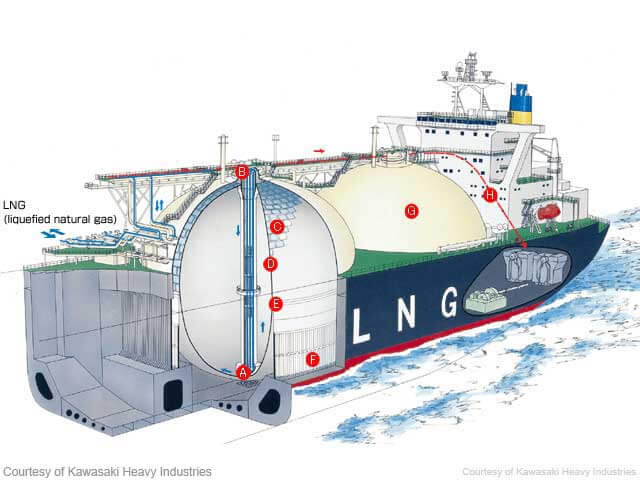
5. LNG ships
LNG carriers are specialised types of gas carriers built to transport large volumes of LNG at its atmospheric boiling point of about -162° C.
- These ships are now typically of between 125,000 and 135,000 m3 capacity and are normally dedicated to a specific project. Here they often remain for their entire contract life, which may be between 20-25 years or more.
The containment systems on these ships are mainly of four types:
1. Gaz Transport membrane
2. Technigaz membrane
3. Kvaerner Moss spherical — independent Type ‘B’ , and
4. IHI SPB Tank — prismatic
- All LNG ships have double hulls throughout their cargo length which provide adequate space for ballast.
- Ships fitted with the membrane systems have a full secondary barrier and tanks of the Type ‘B’ design have drip-pan type protection.
- A characteristic common to all LNG ships is that they burn cargo boil-off as fuel.
- Hold spaces around the cargo tanks are continuously inerted, except in the case of spherical Type ‘B’ containment where hold spaces may be filled with dry air provided that there is an adequate means for inerting such spaces in the event of cargo leakage.
- Most LNG carriers have steam turbine propulsion plants.
CARGO CONTAINMENT SYSTEMS
A cargo containment system is an overall arrangement for containing cargo including, where fitted:
- A primary barrier (the cargo tank),
- Secondary barrier (if fitted),
- Associated thermal insulation,
- Any intervening spaces, and
- Adjacent structure, for the support of these elements.
For cargoes carried at temperatures between -10°C and -55°C the ship’s hull may act as the secondary barrier and in such cases, it may be a boundary of the hold space. The basic cargo tank types utilized on board gas carriers are in accordance with the list below:
Independent tanks
Independent tanks are completely self-supporting and do not form part of the ship’s hull structure. Moreover, they do not contribute to the hull strength of a ship. As defined in the IGC Code, and depending mainly on the design pressure, there are three different types of independent tanks for gas carriers: these are known as Types ‘A’, ‘B’ and ‘C’.
Type ‘A’ tanks
Type ‘A’ tanks are constructed primarily of flat surfaces. The maximum allowable tank design pressure in the vapour space for this type of system is 0.7 barg; this means cargoes must be carried in a fully refrigerated condition at or near atmospheric pressure (normally below 0.25 barg).
Figure below shows a section through this type of tank as found on a fully refrigerated LPG carrier. This is a self-supporting prismatic tank which requires conventional internal stiffening. In this example the tank is surrounded by a skin of foam insulation. Where perlite insulation is used, it would be found filling the whole of the hold space.
The material used for Type ‘A’ tanks is not crack propagation resistant. Therefore, in order to ensure safety, in the unlikely event of cargo tank leakage, a secondary containment system is required. This secondary containment system is known as a secondary barrier and is a feature of all ships with Type ‘A’ tanks capable of carrying cargoes below -10°C.
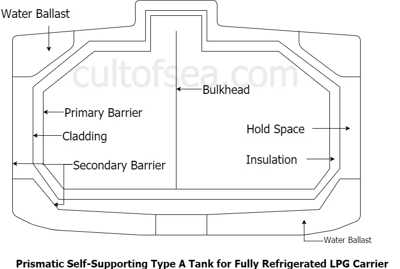
For a fully refrigerated LPG carrier (which will not carry cargoes below -55°C) the secondary barrier must be a complete barrier capable of containing the whole tank volume at a defined angle of heel and may form part of the ship’s hull, as shown in the figure. By this means appropriate parts of the ship’s hull are constructed of special steel capable of withstanding low temperatures. The alternative is to build a separate secondary barrier around each cargo tank. The IGC Code stipulates that a secondary barrier must be able to contain tank leakage for a period of 15 days.
On such ships, the space between the cargo tank (sometimes referred to as the primary barrier) and the secondary barrier is known as the hold space. When flammable cargoes are being carried, these spaces must be filled with inert gas to prevent a flammable atmosphere being created in the event of primary barrier leakage.
Type ‘B’ tanks
Type ‘B’ tanks can be constructed of flat surfaces or they may be of the spherical type. This type of containment system is the subject of much more detailed stress analysis compared to Type ‘A systems. These controls must include an investigation of fatigue life and a crack propagation analysis. These tanks may be able to withstand pressures up to 2 barg. The most common arrangement of Type ‘B’ tank is a spherical tank as illustrated in Figure 3.2. This tank is of the Kvaerner Moss design. Because of the enhanced design factors, a Type ‘B’ tank requires only a partial secondary barrier in the form of a drip tray. The hold space in this design is normally filled with dry inert gas. However, when adopting modern practice, it may be filled with dry air provided that inerting of the space can be achieved if the vapour detection system shows cargo leakage. A protective steel dome covers the primary barrier above deck level and insulation is applied to the outside of the tank. The Type ‘B’ spherical tank is almost exclusively applied to LNG ships; seldom featuring in the LPG trade.
A Type ‘B’ tank, however, need not be spherical. There are Type ‘B’ tanks of prismatic shape in LNG service. The prismatic Type ‘B’ tank has the benefit of maximising ship hull volumetric efficiency and having the entire cargo tank placed beneath the main deck. Where the prismatic shape is used, the maximum design vapour space pressure is, as for Type ‘A tanks, limited to 0.7 barg.
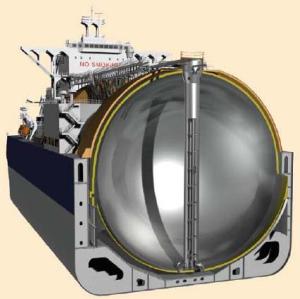
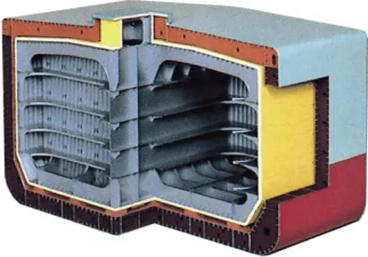
Cross Section View of Type B Tank Ship
Type B Tank being installed into ships hold
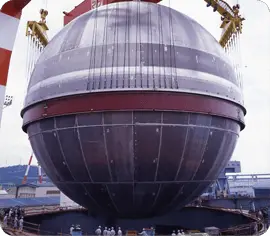
Spherical Tank IMO Type B
Type ‘C’ tanks
Type ‘C’ tanks are normally spherical or cylindrical pressure vessels having design pressures higher than 2 barg. The cylindrical vessels may be vertically or horizontally mounted.
This type of containment system is always used for semi-pressurised and fully pressurised gas carriers. Type ‘C’ tanks are designed and built to conventional pressure vessel codes and, as a result, can be subjected to accurate stress analysis. Furthermore, design stresses are kept low. Accordingly, no secondary barrier is required for Type ‘C’ tanks and the hold space can be filled with either inert gas or dry air.
In the case of a typical fully pressurised ship (where the cargo is carried at ambient temperature), the tanks may be designed for a maximum working pressure of about 18 barg. For a semi-pressurised ship the cargo tanks and associated equipment are designed for a working pressure of approximately 5 to 7 barg and a vacuum of 0.5 barg. Typically, the tank steels for the semi-pressurised ships are capable of withstanding carriage temperatures of -48°C for LPG or -104°C for ethylene. (Of course, an ethylene carrier may also be used to transport LPG.)
Figure below shows Type ‘C’ tanks as fitted in a typical fully pressurised gas carrier. With such an arrangement there is comparatively poor utilisation of the hull volume; however, this can be improved by using intersecting pressure vessels or bi-lobe type tanks which may be designed with a taper at the forward end of the ship.
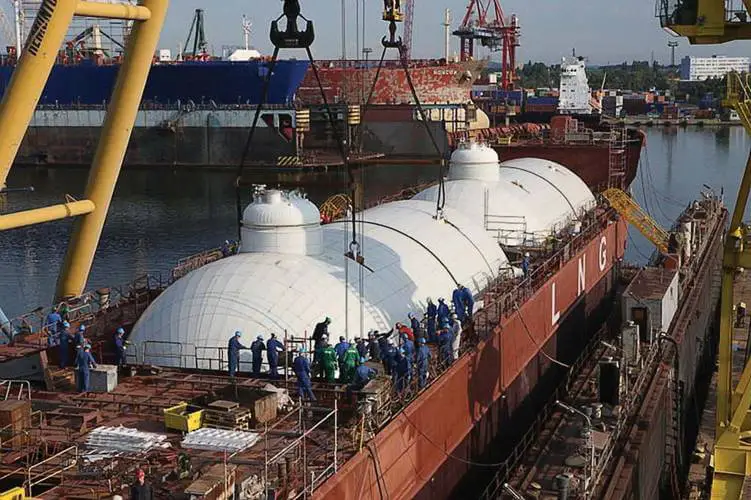
A Type C Tank being installed.
A ship under construction in shipyard with IMO Type C Tanks
Membrane tanks (membrane – 0.7 to 1.5 mm thick)
The concept of the membrane containment system is based on a very thin primary barrier (membrane – 0.7 to 1.5 mm thick) which is supported through the insulation. Such tanks are not self-supporting like the independent tank & an inner hull forms the load-bearing structure. Membrane containment systems must always be provided with a secondary barrier to ensure the integrity of the total system in the event of primary barrier leakage. The membrane is designed in such a way that thermal expansion or contraction is compensated without over-stressing the membrane itself.
There are two principal types of membrane system in common use
- Gaz Transport membrane system
- Technigaz membrane system
Both named after the companies who developed them and both designed primarily for the carriage of LNG.
Initially, the Moss system was more popular, but higher Suez toll fees due to their higher gross tonnage made Moss vessels less attractive for trades involving the Suez Canal. Recently Moss has staged a comeback and currently, there are about 30 Moss vessels on order against 100+ membrane vessels. A fourth LNG containment system joined the ranks of the large marine LNG cargo tank designs in the early 1990’s; the Japanese IHI SPB (Self-supporting Prismatic shape IMO type-B) system. With only two orders for LNG carriers in the 1990’s, this system seemed to be inaccessible due to its high price. However, in 2014 four vessels were ordered with the SPB system, bringing it back as a credible alternative to the membrane systems and the Moss system.
Membrane systems
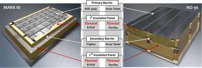
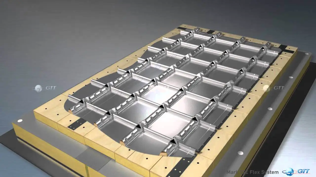
Technigaz designed a membrane type atmospheric LNG containment system with a corrugated stainless steel primary membrane supported by wooden boxes filled with insulation material. A secondary cryogenic barrier, also supported by wooden boxes filled with insulation material provides containment of the cryogenic cargo in case the primary membrane develops a leak. The characteristic corrugations in the primary membrane allow for the shrinkage of metal under cryogenic temperatures. This design, identified as the Mk I was soon superseded by improved versions and is currently available as the Mk III series from a number of shipyards in Korea and Japan. Soon the Mk V series will be going into production, which replaces the current Triplex secondary barrier with a corrugated stainless steel secondary barrier.
Compatriot Gaztransport designed a rather similar system consisting of a primary membrane supported by insulation in plywood boxes and a secondary membrane, also supported by insulation in plywood boxes. This system was called the No 88 system and featured a primary and secondary membrane of a steel alloy with a negligible contraction coefficient. Improvements have been over the years and the current system is the No 96, which is being used in LNG carriers under construction in Korea and China.
After years of competition, Gaztransport and Technigaz merged to form GTT, which has been developing and promoting both membrane type containment systems in parallel. GTT has licensed these systems to all major LNG carrier builders around the world. The main advantage of the membrane type containment systems is their prismatic shape, which allows these systems to use the space available within the hull of the LNG carrier to a very high degree. With the cargo tanks recessed deep inside the hull under a low trunk deck, membrane type LNG carriers do not need a high deck house to have good visibility. This results in the typical “squat” silhouette of this type of vessels. In France, GTT proposed membrane type LNG fuel tanks for the proposed newbuilding ferry for Brittany Ferries. Unfortunately this project was put on hold for the time being for non-technical reasons.
Both membrane systems have one traditional weakness; their vulnerability for sloshing damage. Sloshing is the motion of the LNG cargo in the tanks as a result of the motion of the vessel due to the effect of waves and wind. In certain circumstances, waves occur in the LNG cargo which upon impact on the tank walls can cause damage to the primary barrier and the boxes supporting the primary membrane. To counter the risk of sloshing damage, GTT advises the operators of membrane ships to operate their ships with tank levels of more than 90% or less than 10%. For applications that require part load operations, such as LNG Floating Storage and Regas Units (LNG FSRU), membrane systems with specially reinforced boxes have been developed.
Gaztransport Designed Membrane Tank featured a primary and secondary membrane of a steel alloy with a negligible contraction coefficient.
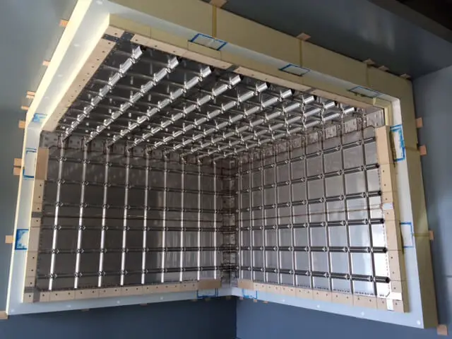
GTT-technology membrane tank model fabricated by Conrad Shipyard.
Cross Section of a Technigaz showing each layer
Technigaz designed a membrane type LNG containment system with a corrugated stainless steel primary membrane supported by wooden boxes filled with insulation material.
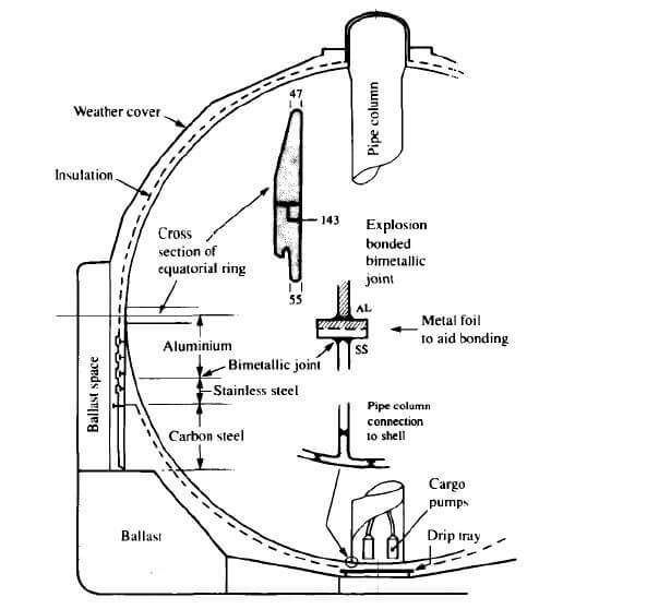
The Moss system
The Moss spherical LNG containment system does not have these sloshing issues. Its aluminium spheres have sufficient structural strength to withstand LNG wave impact due to the interaction between the cargo and the ship’s motion. The Moss system doesn’t need a full secondary barrier like the membrane system; there is only a small drip tray below the spheres to catch any liquid leaking. The design philosophy behind the Moss system is that the tank should be designed to be strong enough so that cracks should not develop in the tanks over the lifetime of the vessel. The structural strength of the containment system is exactly the reason why old Moss vessels are very popular candidates for conversion to LNG FSRU’s or even floating LNG production plants.
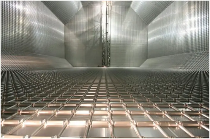
View from inside of Tank
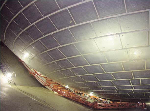
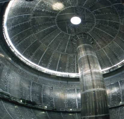
View from inside the hold of ship
The only true disadvantage of the Moss vessels is the fact that the containment system has a very low hull space utilization rate. The sheers are mounted on the deck of the vessel by way of an equatorial ring, which means that half the sphere protrudes above the deck. While this makes for the characteristic silhouette of the Moss carrier, it also necessitates a high deck house to ensure adequate line of sight from the bridge. The low hull space utilization means that a Moss carrier has a higher GT rating than membrane carriers of similar cargo capacity, which translates in higher port and fairway dues and higher tonnage taxes.
The SPB system
The fourth LNG cargo containment system, the IHI (now JMU) SPB system manages to combine the advantages of the membrane system and the Moss system and addresses the disadvantages of both systems too. The prismatic shape of the tanks ensures a high hold space utilization rate and a low air draft, while the solid aluminum construction with a centerline bulkhead and transverse swash bulkheads reduces liquid motion in the tanks and minimizes the risk for sloshing damage, even in part load conditions. The high price of this system originally prevented wide spread adoption but in 2014 JMU, the successor to SPB designer IHI, secured orders for tanks for four 165,000 m3 LNG carriers and it has been addressing the only true disadvantage of this system; its price tag. With possible licensing overseas, the SPB system could become a very serious contender in the LNG containment system arena. In Japan, JMU has already carried out a study with a shipyard into the feasibility of SPB tanks as LNG fuel tanks.
A SPB Tank designed by IHI Japan
“IHI-SPB” (Self-supporting, Prismatic Shape, IMO type B) is Japanese own technology developed by IHI Group while the competing technologies used for LNG floaters including LNG carriers by Japanese and Korean shipyards are imported from Europe (Norwegian Moss technology and French Membrane technology). “IHI-SPB” has unique features of “No Sloshing” which enables any level loading of LNG inside the tank at offshore, “Flat upper deck” which enables installation of the topside plants on upper deck, “Less and Easy Maintenance”, etc. and is most suited to use in the LNG floaters including FLNG and FSRU required to stay offshore and operate safely for long years without dry docking.
Integral tanks
Integral tanks form a structural part of the ship’s hull and are influenced by the same loads which stress the hull structure. Integral tanks are not normally allowed for the carriage of liquefied gas if the cargo temperature is below -10°C. Certain tanks on a limited number of Japanese-built LPG carriers are of the integral type for the dedicated carriage of fully refrigerated butane.
Internal insulation tanks
Internally insulated cargo tanks are similar to integral tanks. They utilise insulation materials to contain the cargo. The insulation is fixed inside ship’s inner hull or to an independent load-bearing surface. The non-self-supporting system obviates the need for an independent tank and permits the carriage of fully refrigerated cargoes at carriage temperatures as low as -55°C. Internal insulation systems have been incorporated in a very limited number of fully refrigerated LPG carriers but, to date, the concept has not proved satisfactory in service.

